The world in which we live in is surrounded by the analog signals. The temperature, sound that hear, the light that we see are all analog signals. If you want to interact or measure these signal in a digital system like Galileo/Edison, you’ll have to use ADC a.k.a Analog to Digital Converter.
What is analog signal?
The most common signal in nature is analog signal. These are also what is known as “continuous” signal. If you were to record an audio signal somehow and if you looked up for the signal in any point in time of the recording, you would find a value there. That is why these kind of signals are known as continuous i.e., there is no discontinuity in signal at any point in time. It is like the infinite numbers between 0 and 1 (or any other integer pair). There are infinite numbers between those two numbers. Similarly, there are infinite number of “samples” between two times t seconds and (t+1) seconds. In other words, there is no gap in the information that the signal represents within any two arbitrarily selected times. As you can imagine, we will need infinite amount of memory to store all this information to store this data. This problem is solved by what is known as sampling, explained later.
What is ADC?
ADC is the one way bridge from the analog to digital world. It takes the analog signal and makes it available to the digital systems like processors in a way in which it can be consumed by them. Like the GPIOs are ways to capture the digital events (for example, button press, can be off or on), the ADCs are for capturing the analog signals.
How do ADCs work?
The ADCs work by mapping the analog voltage (or current) signal applied to certain numerical value that can be used by the digital system at hand. It achieves this by allocating certain number of bits for representing the analog signal (this defines the resolution of the ADC). It can be 8-bit, 11-bit, 12-bit, 16-bit etc.. and magnitude of the applied signal is represented by a numerical value.
The values of the continuous signals are infinite, the ADC rounds it off to the nearest numerical value which best represents applied voltage this process is known as quantization. Since the analog signals are continuous and to record all this information, we will need infinite amount of RAM (as there are infinite amount of information between two points in time). To overcome this problem, we sample the signal at regular intervals so that the continuous signal now becomes "discrete". Nyquist rate dictates the rate at which the signal is to be sampled so that we do not lose any critical information. As long as Nyquist rate is met, we are safe.
However for this tutorial, the sampling rate does not play any major role as the signal that we will be measuring will be manually controlled and will vary very slowly. The sampling rate is critical in DSP applications and in applications where the signal integrity is integral to proper operation of the system.
Once an analog signal is applied, the signal is represented with a numerical value relative to what is known a “reference voltage”(Vref). Hence the maximum numerical value as output by ADC is same as the voltage applied at the reference voltage. Also this implies that with a given reference voltage, the maximum voltage that you can measure is the reference voltage, Vref.
In Galileo/Edison, the reference voltage is set 5V via the shield and the ADC is of 10 bit resolution and hence the maximum value output by the ADC is 1023 (10 bit ADC; 2^10=1024). The 10-bit resolution is the default one. The ADC on board is capable of 12-bit resolution and can be changed by the user.
If you are interested in knowing more on ADC operation you can refer to many of the on line tutorials available such as this one.
What is this Rotary angle sensor?
Grove Rotary angle sensor, also know as the potentiometer(pot) is a electro-mechanical device with a knob. This knob controls the resistance of the pot. It is a three terminal device, first terminal is connected to Vcc (5V or 3.3V) middle pin is connected to the ADC input (in our case) and the last pin is connected to the ground.
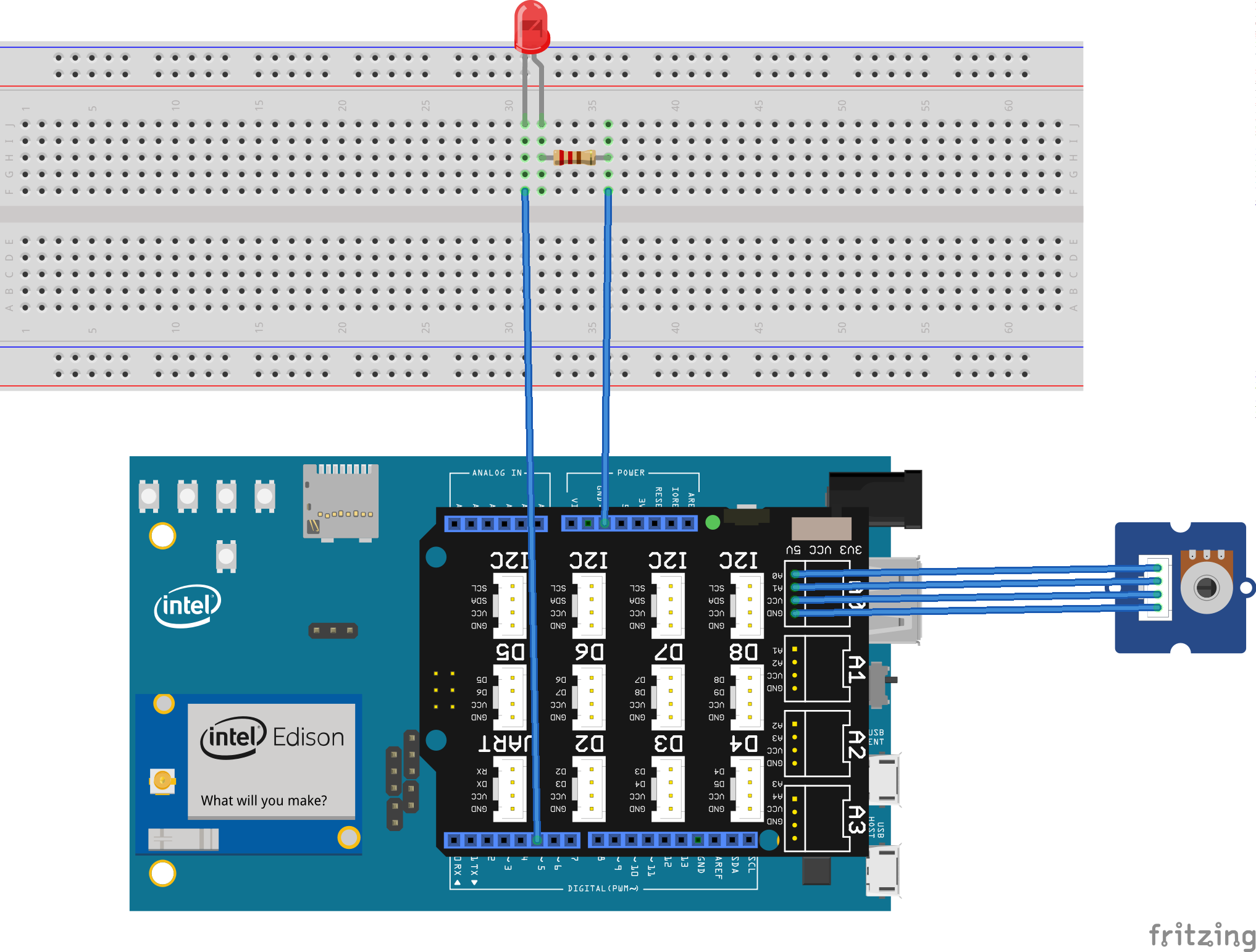
The knob controls resistance at the ADC input point (the middle pin, this forms a voltage divider circuit) there by changing the voltage as measured at the middle pin and the ground in accordance to the Ohm's law. The Ohm's law simply states that the voltage across a circuit is directly proportional to the current flowing through the circuit. The constant in this relation is the resistance. Mathematically put, it is V=I*R where V stands for voltage, I and R stands for current and resistance respectively. As you can easily see varying R has a direct impact on the voltage across the device. While this is a simple explanation, the actual voltage measured will be dependent on the both the resistances created on either side of the moving probe. The knob controls the position of the probe labeled as A0 in the above diagram this positions the "probe" in different positions, changing resistance which results in varying voltage measured across the pins A0 and ground. This change in voltage across these points (A0 and GND) is what will be measured by the Galileo/Edison.
Hardware connections
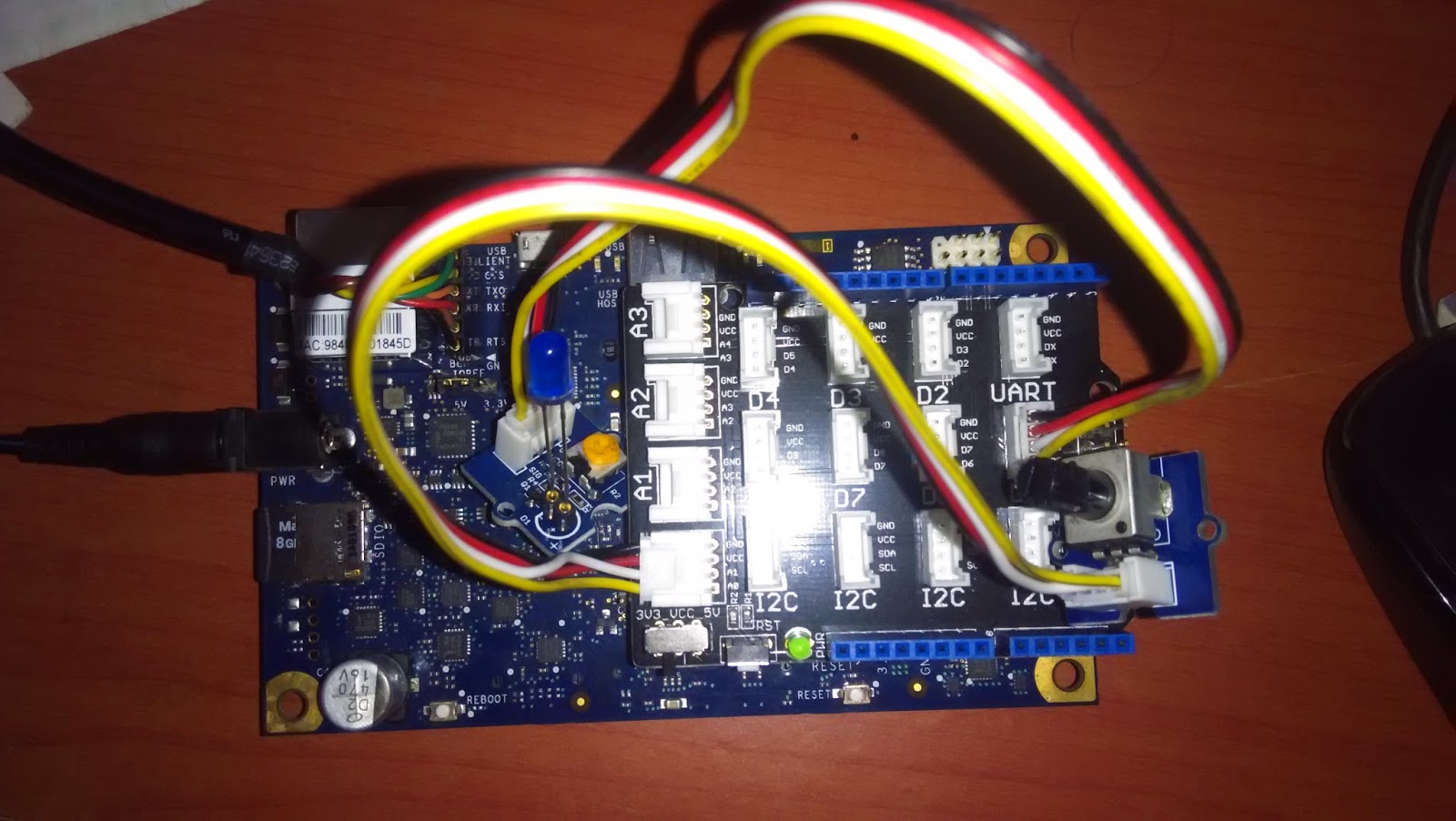
Connect an LED via limiting resistor (or Grove LED module) to port D5 and connect rotary angle sensor to analog port A0.


The program
This piece of code lets to control the brightness of an LED connected to port D5 using a "rotary angle sensor" connected to A0.
#include <mraa.h>
#include <signal.h>


#define PWM_PIN      5        /**< The pin where the LED is connected */
#define ADC_PIN      0        /**< The ADC pin */
#define ADC_MAX   (1024.0)    /**< Maximum value output by a 10-bit ADC */

volatile int keepRunning;

/** Signal handler used to stop this application cleanly */
void handler(int arg)
{
    (arg);
    keepRunning = 0;
}


int main(void)
{
    mraa_pwm_context       pwmPin;   /* The PWM pin context */
    mraa_aio_context       adcPin;   /* ADC pin context */

    float                  intensity; /* Intensity with which LED is to glow */
    float                  adcValue;  /* Read ADC value */

    /* Step1: Intialize the mraa system */
    mraa_init();

    /* Step2: Initalize analog port 0 for ADC operation */
    adcPin = mraa_aio_init(ADC_PIN);

    /* Step3: Initialize D5 for PWM operation */
    pwmPin = mraa_pwm_init(PWM_PIN);

    /* Step4: Set the period on the PWM pin */
    mraa_pwm_period_us(pwmPin, 5000);      // Set the period as 5000 us or 5ms

    /* Step5: Enable the PWM pulse on the pin */
    mraa_pwm_enable(pwmPin, 1);

    keepRunning = 1;

    /*
     * Associate ctrl+c with our handler that clears the 'keepRunning'
     * flag that allows us to stop the PWM and ADC when exiting
     */
    signal(SIGINT, handler);

    while (keepRunning)
    {
        /* Step6: Read the ADC value using the function 'mraa_aio_read()' */
        adcValue = mraa_aio_read(adcPin);
        intensity = adcValue/ADC_MAX;
        /* Step7: Set the intensity of the LED at port D5 using PWM */
        mraa_pwm_write(pwmPin, intensity);
        usleep(500);
    }

    /* Step8: Stop the PWM and ADC when not required */
    mraa_pwm_enable(pwmPin, 0);
    mraa_aio_close(adcPin);

    return 0;
}
As usual, the "mraa.h" is included for the function prototypes of the ADC and PWM pins required. The ADC_PIN and PWM_PIN are set as 0(A0) and 5(D5) respectively. We are going to use the ADC in 10-bit mode hence the ADC_MAX is set as 1024, which will be used in later calculations.
#include <mraa.h>
#include <signal.h>


#define PWM_PIN      5        /**< The pin where the LED is connected */
#define ADC_PIN      0        /**< The ADC pin */
#define ADC_MAX   (1024.0)    /**< Maximum value output by a 10-bit ADC */
A variable called as "keepRunning" is defined that will be used as flag which will be used to stop the demo.
Then we define signal handler as in previous tutorial that will subscribe to "ctrl+c" key press event. Hitting this particular chord key, will call this defined function, "handler". Within this function, we will clear the flag "keepRunning" to stop the demo and subsequently properly shutdown the PWM and ADC channels.
void handler(int arg)
{
    (arg);
    keepRunning = 0;
}
Now within main, the mraa system is initialized and the PWM and ADC contexts are created and initialized. Using "mraa_aio_init()", the ADC pin context is created. This function accepts the ADC pin number as input and returns the ADC pin context.
    mraa_init();
    adcPin = mraa_aio_init(ADC_PIN);
    pwmPin = mraa_pwm_init(PWM_PIN);
Once we have PWM context ready to be used, the period of the PWM pin is set and the PWM pulse train is enabled on that pin.
    mraa_pwm_period_us(pwmPin, 5000);      // Set the period as 5000 us or 5ms
    mraa_pwm_enable(pwmPin, 1);
The "keepRunning" flag is set indicating we have to run the LED control loop, then the signal handler association is made.
    keepRunning = 1;
    signal(SIGINT, handler);
Now comes the main control loop code path. Here in a loop controlled by the "keepRunning" flag.
    while (keepRunning)
    {
        /* Step6: Read the ADC value using the function 'mraa_aio_read()' */
        adcValue = mraa_aio_read(adcPin);
        intensity = adcValue/ADC_MAX;
        /* Step7: Set the intensity of the LED at port D5 using PWM */
        mraa_pwm_write(pwmPin, intensity);
        usleep(500);
    }
The ADC value is read into the variable "adcValue" using the mraa API mraa_aio_read() this function accepts the ADC pin context as input and returns the read digital value. Thus read ADC value is normalized to be used as duty cycle, using the variable "intensity".
When "ctl+c" is singal is received, the "keepRunning" flag will be cleared and the while() loop exits. Outside of this loop, the PWM and ADC is stopped and the program exits thereafter.
  mraa_pwm_enable(pwmPin, 0);
  mraa_aio_close(adcPin);
Compiling and running the example:
Use the wget from within the Edison console to get this individual file:
wget https://raw.githubusercontent.com/navin-bhaskar/C-CPP-on-Intel-Edison-Galileo/master/part4-adc/adc.c
Or use git to clone the repository that I have created for all the code examples from this tutorial series and navigate to part4-adc
git clone https://github.com/navin-bhaskar/C-CPP-on-Intel-Edison-Galileo.git tutorial
cd tutorial
cd part4-adc
Now that you have the source compile it using following command
gcc -o adc adc.c -lmraa
run the program
./adc
Vary the rotary angle sensor to change the LED intensity hit "ctrl+c" to exit.
No comments:
Post a Comment